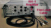
The ECG signal will be recorded
through the ISO-1 isolated input amplifier unit in the
interface box. A five-lead patient cable is connected
to the input of the ISO-1 amplifier.
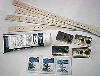
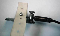
Four plate electrodes with
associated straps, a tube of electrolyte paste, and alcohol
pads are also required.
Procedure
The subject should lie flat on
his/her back on a bench or cot, with hands at their
sides.
The inner aspect of the right
forearm just above the wrist is rubbed briskly with
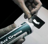
alcohol. A small drop of electrolyte paste is squeezed
onto a plate electrode and is spread evenly over the surface
of the electrode.
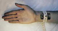
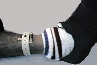
The electrode is then
placed onto the cleansed area, and secured to the arm using
the rubber strap provided.
The above is repeated for the
left arm, and then for both legs, attaching the electrodes a
few inches above the subject's ankles.
The appropriate leads
of the patient cable are attached to the binding posts on the
plate electrodes as follows:
LA (black plug) to plate on left
arm
RA (white plug) to plate on
right arm
LL (red plug) to plate on left
leg
RL (green plug) to plate on
right leg
The ECG/EMG switch on the ISO-1
is set to ECG. The gain control is turned to about
mid-position. Lead II is
selected on the lead-selector switch.
The Three Standard Bipolar Limb
Leads
When the lead selector
switch on the ISO-1 module is switched to the position
labelled II, the
LL electrode is taken to the + terminal of the amplifier, and
the RA electrode is taken to the - terminal of the
amplifier. Thus the output called Lead
II is the difference in the potentials
appearing on the left leg and the right arm:
Lead
II =
(VLL - VRL) -
(VRA - VRL) = VLL
- VRA
Remember that the
potential measured at the right leg (VRL) is
used as the reference potential.
The connections for all
three standard limb leads are shown to the left below.
The figure to the right shows a diagrammatic representation of
the Einthoven Triangle Hypothesis. Willem Einthoven
(1860-1927) attempted to explain the principles of the ECG in
scientific terms. In Einthoven's triangle, the heart may
be considered to lie at the centre of an equilateral triangle
and the corners of the triangles are the effective sensing
points - the right arm, left arm and left
leg.
Einthoven's
Triangle
Lead
I = (VLA - VRL)
- (VRA - VRL) =
VLA -
VRA Lead
II = (VLL - VRL)
- (VRA - VRL) =
VLL -
VRA Lead III = (VLL - VRL)
- (VLA - VRL) =
VLL -
VLA